RGB Controller
This project is a cheaper alternative to other ambilight projects and devices out there. With this light set the only issue is the limitation to a single color at a time. Other light strips have the ability to interpret serial signals where this one functions off a digital RGB signal but, for $30 and some change you can't go wrong.
This project requires some steady hands for a bit of soldering and some minor programming knowledge with Arduino. The Processing code was created from looking through various searches and is just needed for screenshotting and determining an average color from that capture. The Arduino and Processing code is available on my GitHub. Both files are in the same repository.
The Basics
What You'll Need
- An Arduino microcontroller. I am using an Arduino Uno for this project but all others should work only some pin change declarations will need to be changed.
- The LED light strip. Mine is from IKEA.
- Arduino IDE and Processing IDE.
- Flat-head screwdriver (or something to open up the LED controller) and a soldering iron for connecting jumper wires to the transistors that control the lighting.
- Optional: A Dremel or something to drill a small hole.
Modifying the LED Controller
Disclaimer: Doing this most likely voids any warranty so proceed at your own risk.
Cracking the controller open takes a little bit of force since there are 4 plastic tabs holding it together. I worked on each corner until it opened a bit and stuck another spare screwdriver in to keep it open and add a little bit of leverage.
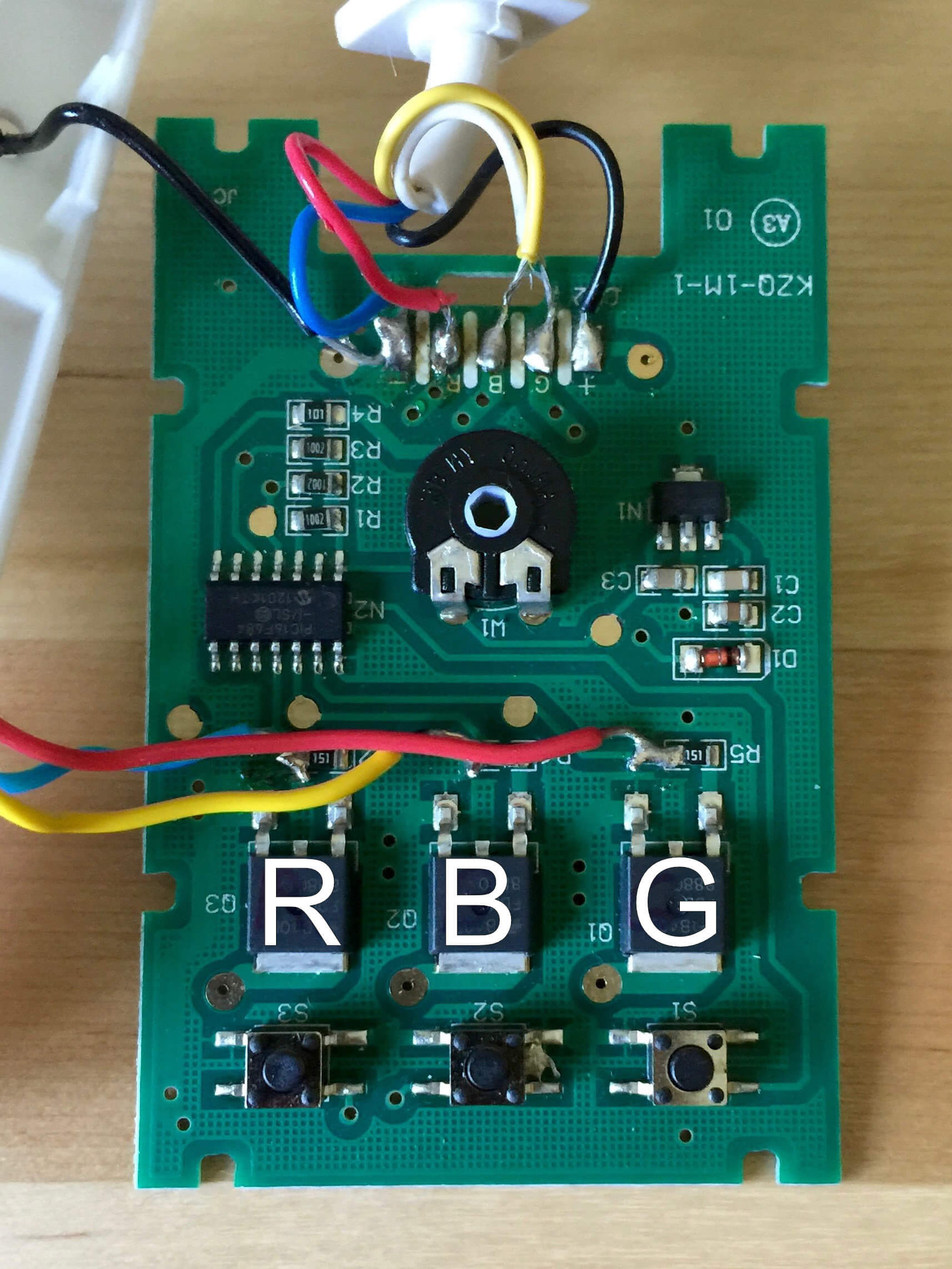
Once it is open the soldering can begin! There are 4 pads that need jumper wires soldered to them. 3 of the 4 belong to the RGB transistors towards the bottom of the board. A jumper wire needs to be placed on the left side of each of the resistors above the transistors. The other jumper wire needs to be soldered to the ground terminal of the board which is at the top and the far left pad marked with a minus sign ( - ).
For added convenience I drilled two small holes into the top of the controller case so it can be closed with the wires sticking out the top. Normal function of the controller will still be available.
Modifying the controller this way also gives the added benefit of using the already connected power supply as the Arduino cannot and should not power all of the LED's.
Software
Download both files from the GitHub link above. Copy the Arduino .ide file to its own folder in your Arduino directory. Copy the Processing .pde file to its own folder within your Processing directory. Both of these folders should be in your C:\Users\YourName\Documents\Arduino or Processing on Windows and Users/yourname/Documents/Arduino or Processing on Mac.
There are a few things that you need to determine before running any of the software. For the jumper wire connections I am using the PWM pins 11 for red, 9 for green, and 10 for blue. This can be changed accordingly based on your microcontroller model, just make sure they are PWM pins. For specifics, lines 16-18
const int redLight = 11;
const int greenLight = 9;
const int blueLight = 10;
Within the Processing code there are a few things that need to be adjusted depending on your setup.
Communication (COM) Port
This is dependent on which USB port your Arduino controller is plugged into. This can easily be found by going to Tools -> Port within the Arduino program IDE. From there it should list the port to communicate with the device. To change the communication port is on line 12.
String comPort = "COM1";Resolution
This should be pretty straightforward, change the width and height values to match your monitors resolution. Changing the resolution is found on lines 15 and 16.
int width = 2560;
int height = 1440;
Sample Divisor
Changing this number will affect the accuracy and speed of the program. Increasing will be faster but less accurate. Decreasing the number will be more accurate but will be slower. I found leaving the divisor at 8 seemed suitable but experimentation with the value is always available. This is found on line 19.
int pixelDivisor = 8;Demo
This is a simple demo of the lights where a single color is being detected and outputted from the computer. Unfortunately, one of the transistors died and the color output wasn't as accurate anymore. There seemed to be a decrease in blue output. As it stood, before the untimely demise, I would call this project complete given the materials on hand. Further improvements could always be made to the code base but at the moment it works well.